Analyze code
Follow these steps to learn how to reverse engineer an application with Dependency and Sequence diagrams, resources provided by Genero Code Analyzer.
-
Right-click the OfficeStore Group node and select Open
Dependency Diagram.
Dependency diagrams display a graphical view of the complex relationships between components of a project and can be opened at the group or application level.
Figure: Option to open a Dependency Diagram 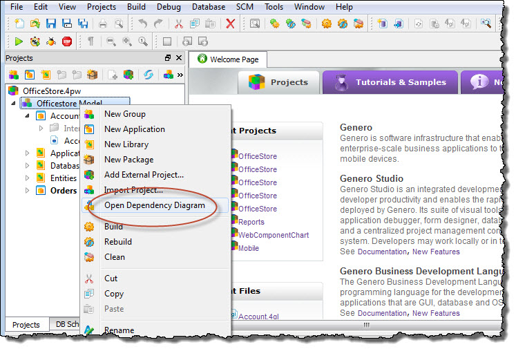
-
Right-click the Entities node in the Dependency diagram and select
Expand from the context menu.
The Entities node expands to display all the sub-components and the relationships between them. Use Ctrl-mouse wheel to zoom in and out.
Figure: The expanded Entities node 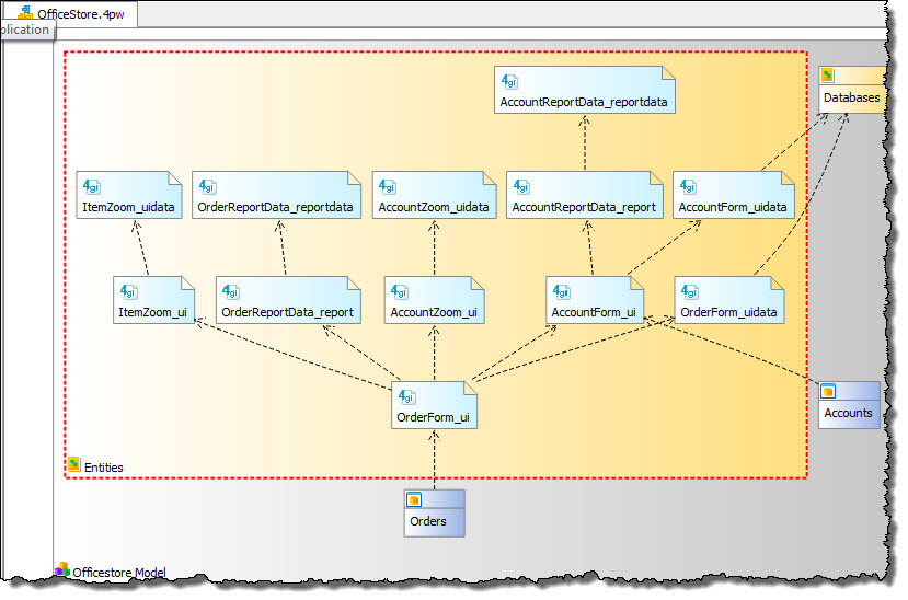
-
Use a Dependency diagram filter to focus on the dependencies between components of the
Accounts application:
- Right-click anywhere in the Dependency diagram margins and select Filter Items...
- In the Select items to filter dialog, deselect Orders.
- Press OK.
Figure: The Filter view 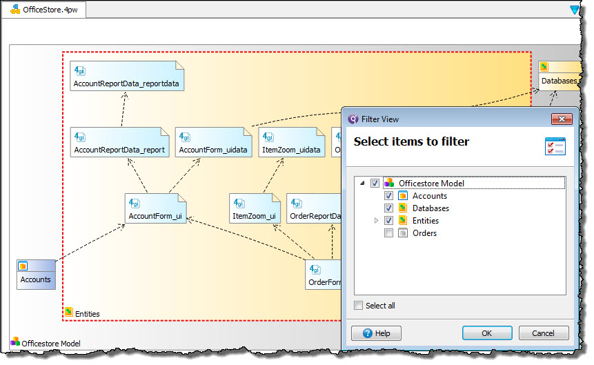
-
Select the link between
AccountForm_uiandAccountForm_uidatato display associated function calls in the Function calls view.Details about function calls between the selected modules are shown in the Function calls view and the project structure displays as a tree in the Dependency Diagram Structure view.Figure: The Function Calls view 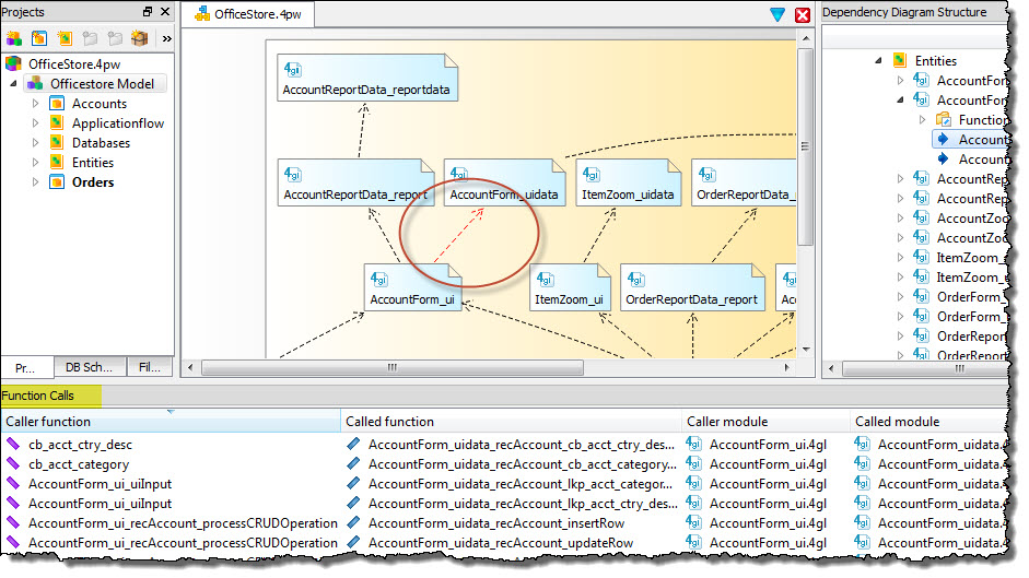
-
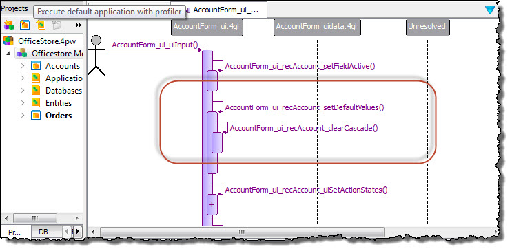
Right-click on the
AccountForm_ui_uiInputfunction in the Function Calls or Dependency Diagram Structure view and select Open Sequence Diagram.The diagram shows the logic flow ofAccountForm_ui_uiInput, with the starting point indicated by the stick-figure representing the user who interacts with the application. The boxes represent functions in the AccountForm_ui.4gl module, and the sequence is indicated by the order in which the boxes are listed. Plus/minus signs on each box allow you to display or hide sub calls.Figure: A Sequence diagram 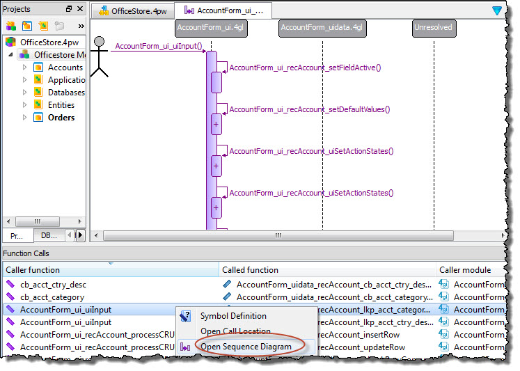
-
Right-click the box for the
AccountForm_ui_recAccount_setDefaultValuesfunction and select Show Sub Calls.The box is expanded to show theAccountForm_ui_recAccount_clearCascade()subcall.Figure: Sequence diagram with expanded function box