Sequence Diagrams
The Sequence Diagram visually displays the flow of your application logic. It shows how the functions of the application call and/or are called by other functions.
Display the Sequence Diagram for a function
To display the Sequence Diagram for a function:- Right-click the function name, in either the opened Genero source code (4gl) file (in Code Editor) or in the Code Structure view.
- Select .Tip: If you do not see the menu option, rebuild your application.
Display the Sequence Diagram for the application
To display the Sequence Diagram for an application:- Right-click the word
MAINin theMAINprogram block in the opened Genero source code (4gl) file (in Code Editor) or in the Code Structure view. - Select . Tip: If you do not see the menu option, rebuild your application.
The Sequence Diagram
Figure: Sequence Diagram
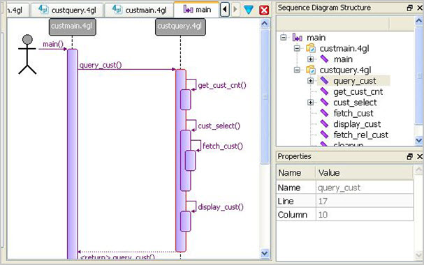
- Processes that exist simultaneously are represented by parallel lines. For a Genero application, these lines represent the source code modules in your application.
- Boxes on the lines represent the functions in each module. The sequence is indicated by the order in which the boxes are listed; functions which are called by other functions have their boxes stacked on top. Plus and minus signs on each box allow you to display or hide sub calls.
- Horizontal arrows display the interaction between functions, the messages (calls) that are exchanged between them, and the order in which the calls occur.
MAIN program block (function),
which calls the query_cust function in the custquery.4gl
source code module. The query_cust functions calls other functions in that module
in the order indicated. For example, it calls the function cust_select, which calls
fetch_cust. The query_cust function returns to the
MAIN.Zoom
Hold down the CTRL key and use the mouse wheel to zoom in and out of the diagram.
Structure View
The structure of the program modules is shown in a tree in the Structure view. Use the plus/minus signs to display/hide the functions in a module. Select a function in the Structure view to display its properties in the Properties view. Right-click on a node in the Structure view to see a context sensitive menu of options for that node.
Sub Calls
Right-click on the sequence diagram to display the menu options that will display or hide all the sub calls in a program.
Customize
Use to define default maximum number of dependencies; default is 1.