Dependency Diagrams
The dependency diagram displays the relationships between the various pieces of a project. It shows the components that depend on other components, or have components that depend on them.
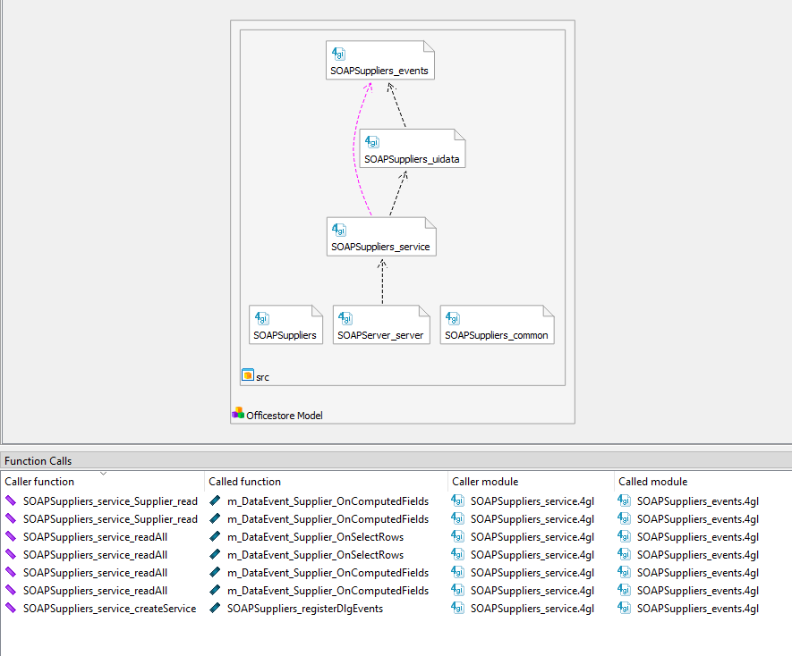
To display a dependency diagram, right-click an application, library, or group node, and select Open Dependency Diagram. The diagram displays as in Figure 1.

When you select an item in the dependency diagram, it is highlighted in the Dependency Diagram Structure tree, and its properties are shown in the Properties view.
- Zoom in and out by holding down the Ctrl key while using the mouse wheel.
- Right-click on an item and select Expand to show all the item's subcomponents.
- Right-click on an item or the background and select Collapse to hide subcomponents.
- Right-click and select Filter Items to choose items to show or hide.
Function Calls
The dependency diagram provides easy access to the functions of the application. Select the link (arrow) between items in the diagram to display the associated function calls and modules in the Function Calls view.
From the Function Calls view, use the context menu go directly to the source code:
- To open the source file, right-click the Caller or Called module name and select View source.
- To go to the definition of a function and its variables in the source file, right-click the Caller or Called function name and select Symbol definition.
- To go to where a function is called in the source file, right-click the Caller function name and select Open call location.
You can also use the context menu to open the sequence diagram for the caller or called function.